| ELGEO LLP Development and production of the equipment for seismic exploration, seismic monitoring and seismology Almaty. Republic of Kazakhstan |
| Main page | New production | Downloads | Contacts | Russian English |
| Network system of seismic monitoring of NSSM |
| Some results of use of systems of seismic monitoring |
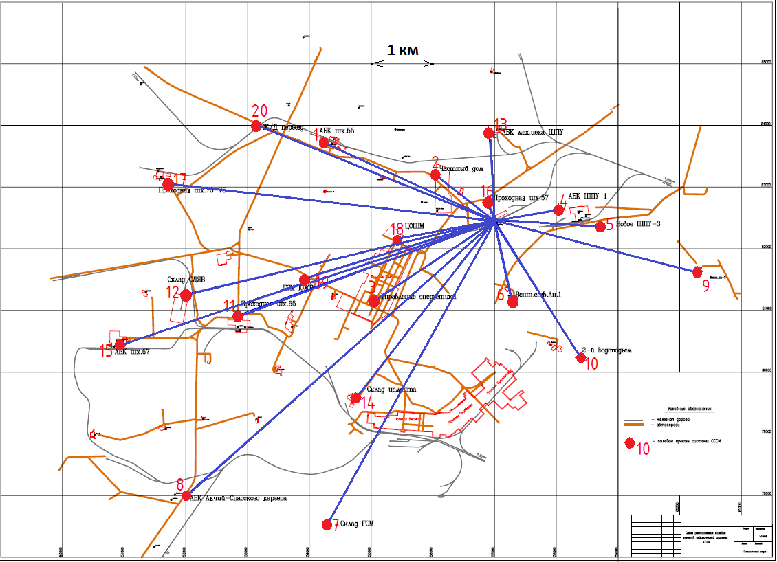
Network system of seismic monitoring NSSMSystem designation of NSSM The network system of seismic monitoring NSSM (NSSM system) manufactures of Elgeo LLP is intended for the organization of monitoring of seismic activity for the regional forecast of a shock hazard of sites of the massif of rocks and ores. The NSSM system is the technical tool used at realization of actions of protection against the emergency situations bound to development of mineral deposits. In Kazakhstan the systems of seismic monitoring are already used on some fields. Use of systems of seismic monitoring on all fields of ore minerals where production is made in underground excavations is perspective. Economic effect of use of system of seismic monitoring consists in decrease or prevention of damage from emergency situations, the bound to a collapse of underground excavations. The well-timed forecast allows to bring personnel and an expensive inventory out of a dangerous zone in advance, to execute other protective measures and, thus, to prevent costs of restitution of an inventory, payment of compensations by the victim which can be the considerable. The range of application of the NSSM system is not limited only a shock hazard fields of solid minerals. The NSSM system can be applied to monitoring of harbingers of emergency situations everywhere where as a harbinger of emergency situation serve the physical phenomena causing emergence of seismic waves, for example accidents on oil fields, the bound to formation of underground emptiness at oil recovery, accident on oil pipelines and others. Principle of work of the NSSM system The forecast of a shock hazard of sites of the massif of rocks and ores is based on the common regularity of development of geomechanical processes per which infrequent important events (a collapse of large volumes of the massif) are prepared bymany more shallow events (emergence micro and macrocracks, breaks). Therefore, to predict emergence of large-scale destructions, it is necessary to monitor constantly accumulation of shallow damages of the massif of rocks. One of ways of such tracking is filing of seismic events - the geodynamic phenomena which are characterized by emergence in the massif of rocks or ores of the seismic waves arising at formation of damages of the massif of rocks with the subsequent calculation of geographical coordinates of their epicenters and assessment of their seismic energy by means of systems of seismic monitoring. The network system of seismic monitoring NSSM consists of network of the seismic units connected in uniform system which allows to reveal within the mine field of a zone, dangerous on mountain blows, based on the continuous filing of parameters of seismic activity. The example of placement of the SSSM system from 20 field points is given in fig. 1.The arrangement of field units is chosen considering the most optimum coverage of objects of seismic monitoring. Possible places of emergence of seismic events must be surrounded with field units of system of seismic monitoring. Density (number of field units of system) gets out to 1 sq.km proceeding from the required error of determination of coordinates of seismic events and sensitivity of system to weak seismic events. Minimum structure of system of seismic monitoring of 6-8 field units.
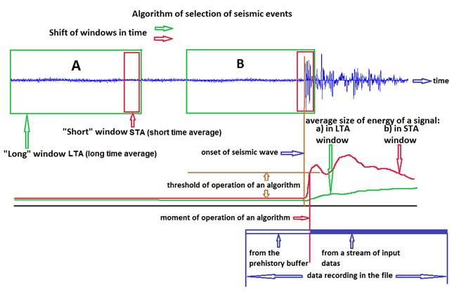
Process of filing of seismic signals, selections and processingТs of seismic events the NSSM system is made as follows. Seismic signals from the geophone enter on an input of field unit. In field unit, their amplification, digitization is made. The digitized seismic signals are exposed to a digital filtration. Then the digitized signals are formed in blocks of data which are supplied with a tag of date and time from the firmware highly stable digital watch. These clocks are synchronized from the means of synchronization of time which are available as a part of system. Blocks of the digitized seismic data come to the firmware computer of field unit where register in daily files. Daily files are files in which contains on one hour of seismic data. In process of filling of micro SD Ц cards of the firmware computer, aged files are removed, making room for new files. Volume of SD-cards is sufficient for storage of several days of record. In parallel with file recording, seismic data are exposed to the analysis for selection of a seismic event on the algorithm known as STA-LTA. The idea of an algorithm of selection of a seismic event consists in the following, fig. 2. During reception of a seismic signal calculation of power of a signal by averaging of squares of counting of a signal in short (1 Е 3 sec.) Ц Short Time Average, STA and in the lengthiest (10 Е 20 sec.) Ц Long Time Average, LTA, windows are made. In the lengthiest window, average energy of a signal changes smoothly, and, presumably, reflects the level of micro seismicnoise. In a short window, average energy of a signal changes more sharply therefore at receipt of a signal from a seismic event will show larger value in relation to the lengthiest window. In fig. 2 two provisions of the lengthiest and short windows concerning the recorded signal are shown. For lack of a seismic event (situation A) mean value of energy of a signal in windows is identical, at receipt of a signal from a seismic event (the provision of windows B) the average size of energy in a "short" window grows quicker, then in the lengthiest. If this body height exceeds the given threshold of rather average size of energy in the "lengthiest" window, then the fact of existence of a seismic event is fixed, and the message on a seismic event and time of its fixing is sent on the server. The specified algorithm "de facto" is the international standard and is applied in all digital equipment intended for the filing of seismic events released in the world. The algorithm is not deprived of shortcomings and can have the considerable number of malfunctioningТs. The number of malfunctioningТs can be reduced by selection of length of windows and a threshold of operation. For decrease of number of chance events, the server after obtaining the message on an event expects messages on a seismic event from other field units. If during the given period of time (1 Е 3 c) the given number worked (3. 6) other field units, the server defines time of a seismic event and gives to field units the command to send seismic data for the given period of time. If the number of the worked field units less the given, the message on a seismic event is ignored. As at the time of operation of an algorithm the event already took place not to lose the beginning of an event, the server requests data with shift on time back for the period of background (2 Е 5 sec.). The data obtained from different field units unite in one data recording of a seismic event and remain in the database.
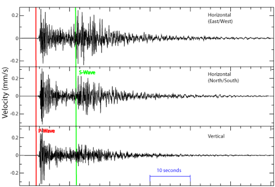
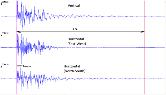
Data processing is made by the operator in the interactive mode. In processing the operator by the form of wave forms at first defines whether record is record of a seismic event, or this chance event. If record is a seismic event, then its processing in the interactive mode is made. During formation of a seismic event (phenomenon) in the thickness of rock there are two types of elastic waves - a longitudinal P-wave and a transversal S-wave which extend with different speeds - the S-wave has smaller speed. Therefore, on a difference oftimes of arrival of a P-wave and a S-wave in a point of observation it is possible to calculate distance to epicenter of the seismic phenomenon. When filing seismic waves in several various points it is possible to build for each point the sphere with a radiusequal to the received distance from an observation point to epicenter of a seismic event. Location coordinates of crossing of these spheres will also be coordinates of a seismic event. In a filing point the geophone the transversal S-wave comes to seismology when deal with the analysis of the earthquakes which occurred for hundreds of kilometerswhen the fluctuations caused by the come first longitudinal P-wave already sufficientlycalm down (Fig. 3). Therefore, in seismology when filing the P-wave and a S-wave are well divided one from another and the described method of determination of coordinates works. But at use of systems of seismic monitoring for the regional forecast of a shock hazard of sites of the massif of rocks and ores the distance from the place of emergence of a seismic event to a point of filing of seismic waves (field unit of system) does not exceed units of kilometers (see fig. 1.). In these conditions on a seismogram the onset of a transversal S-wave is imposed on residual fluctuations of a longitudinal P-wave, and precise definition of the moment of the onset of a transverse wave becomes extremely difficult (fig. 4). Therefore, in the NSSM system the algorithm where calculation of coordinates of a seismic event is made only per the onset of a longitudinal P-wave is realized. The algorithm is based on serial search of many options of an arrangement of a source of seismic waves in all territory captured by the NSSM system.
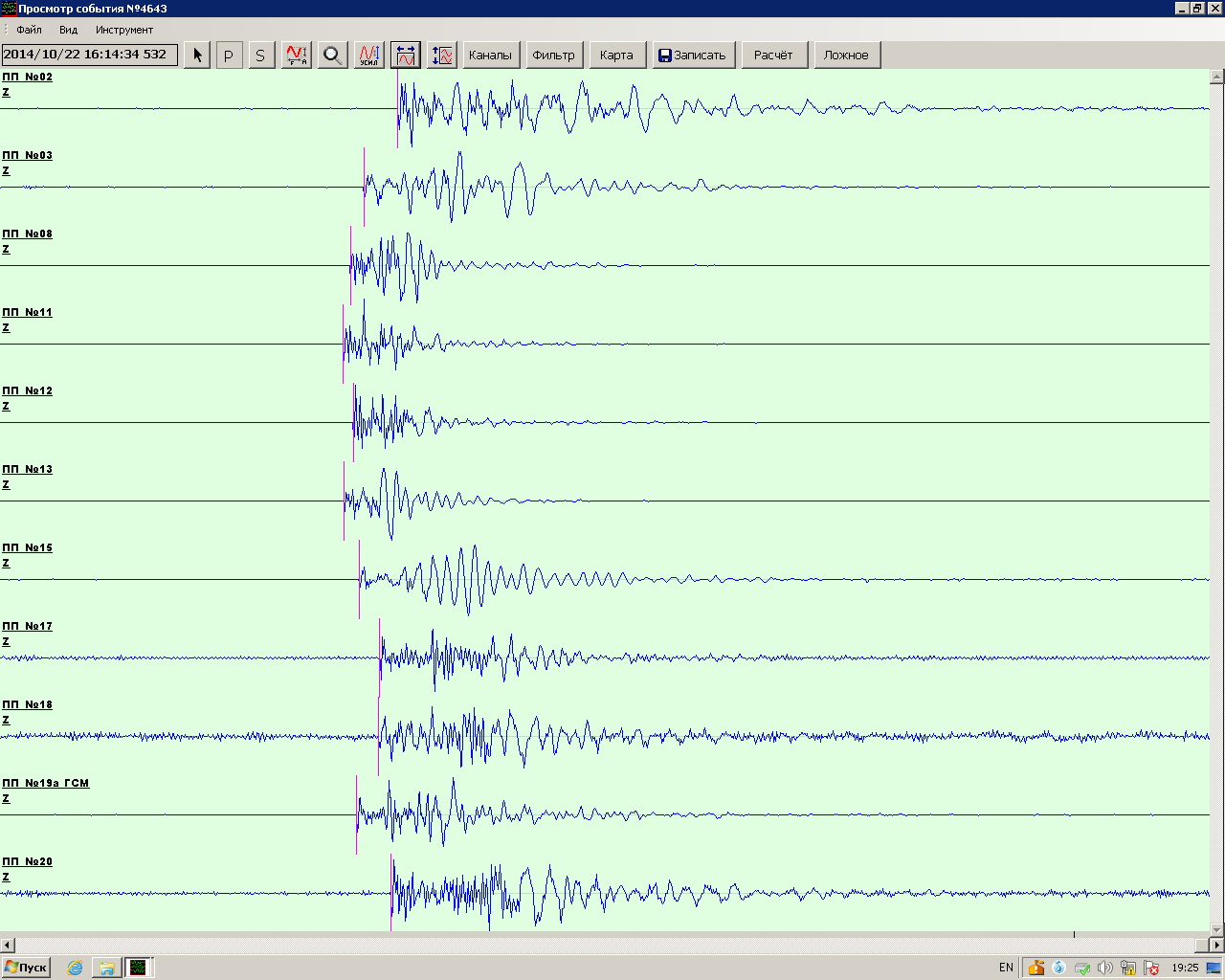
The example of processing is shown in fig. 5. The operator manually points the moments of the onset of waves (red tags to fig. 5), then starts the procedure of calculation. ProcessingТs are result geographical coordinates of epicenter and a power class (seismic energy) of a seismic event. Results of processing remain in the database.
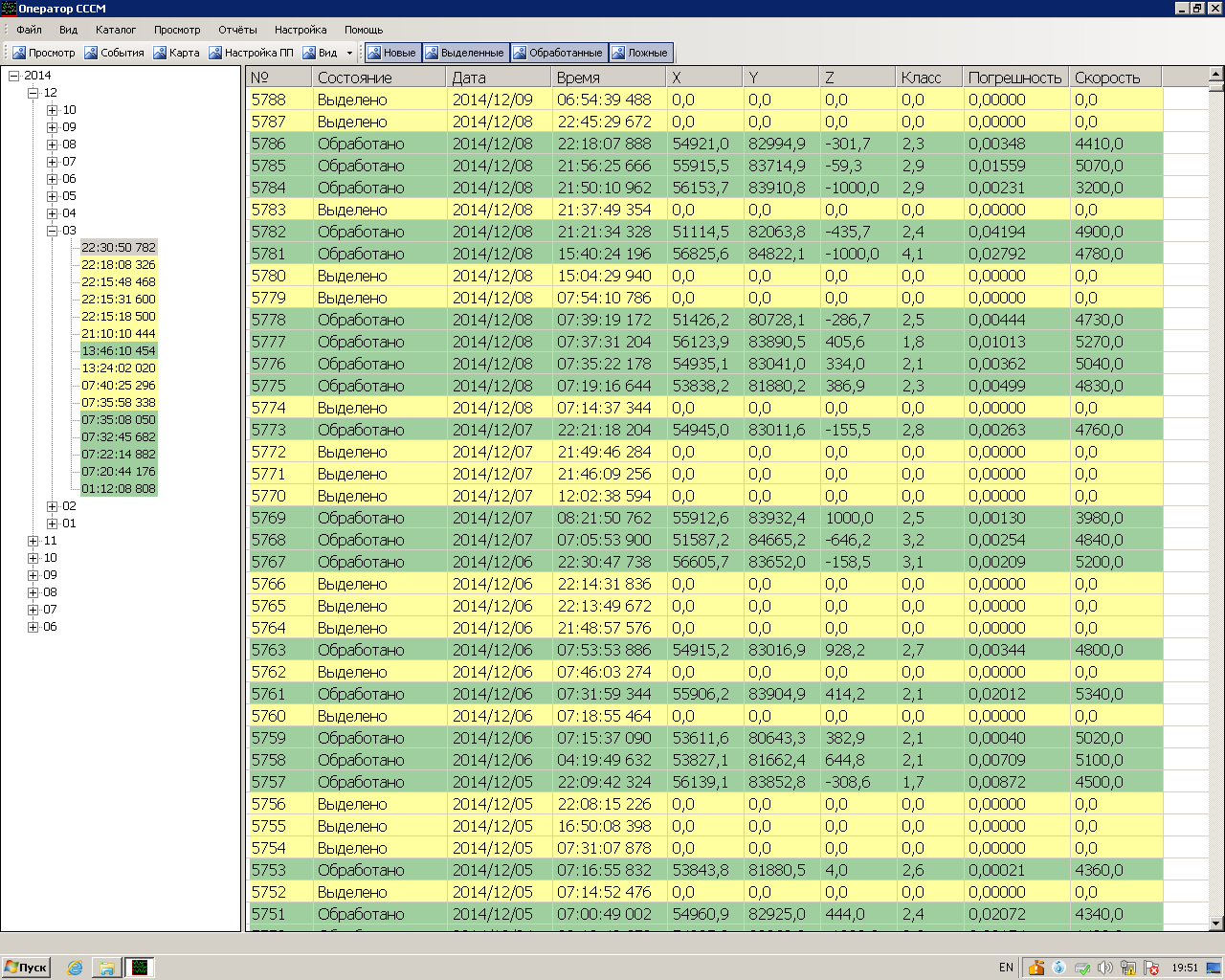
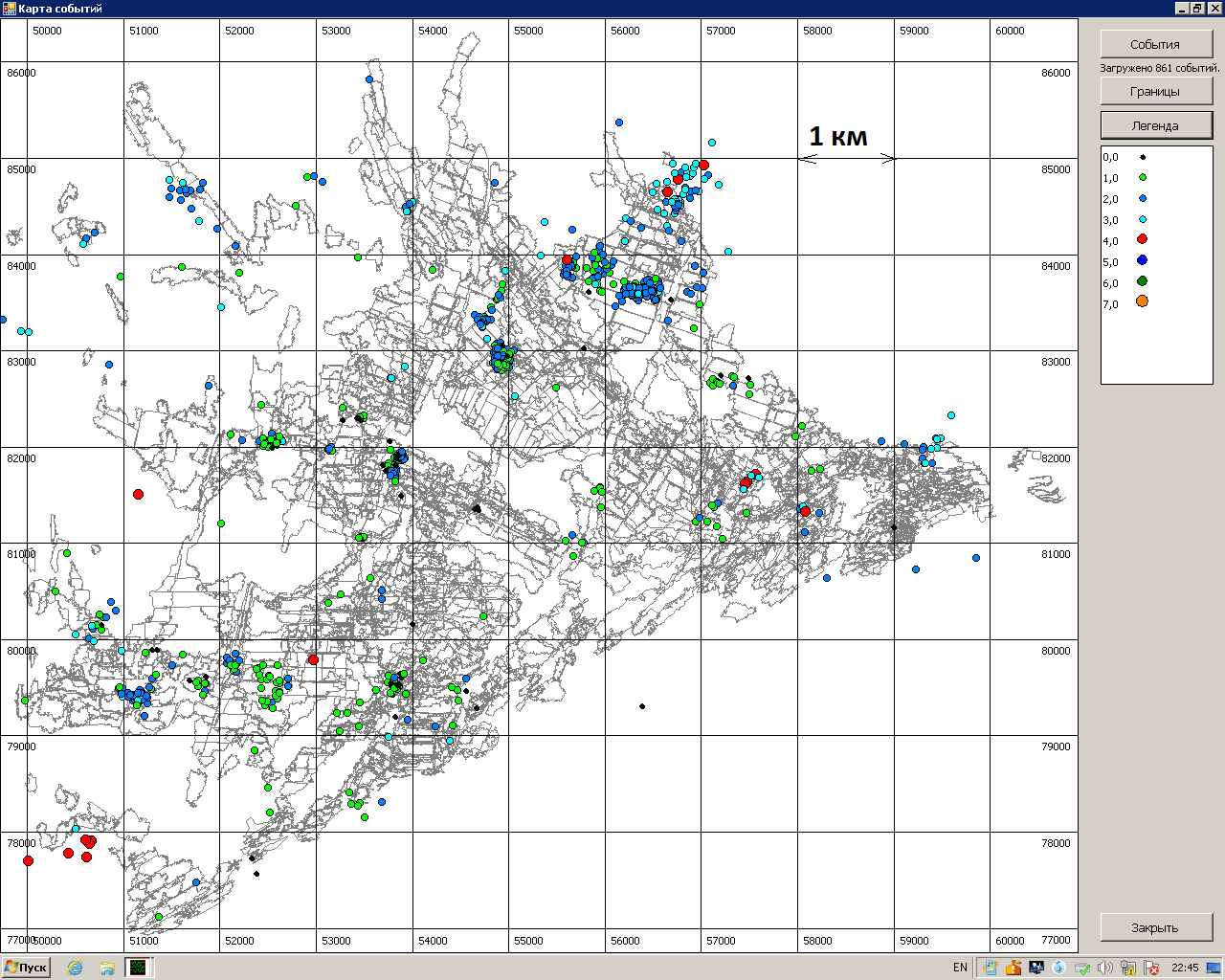
The catalog of the registered events is shown in fig. 6. Display of seismic events on the plan of mining operations per calculation of coordinates is shown in fig. 7. In process of accumulation of data array about seismic events there is possible a forecast of emergency situations. The forecast is not function of the NSSM system, but is under construction the expert the geomechanic based on the data obtained by system of seismic monitoring.
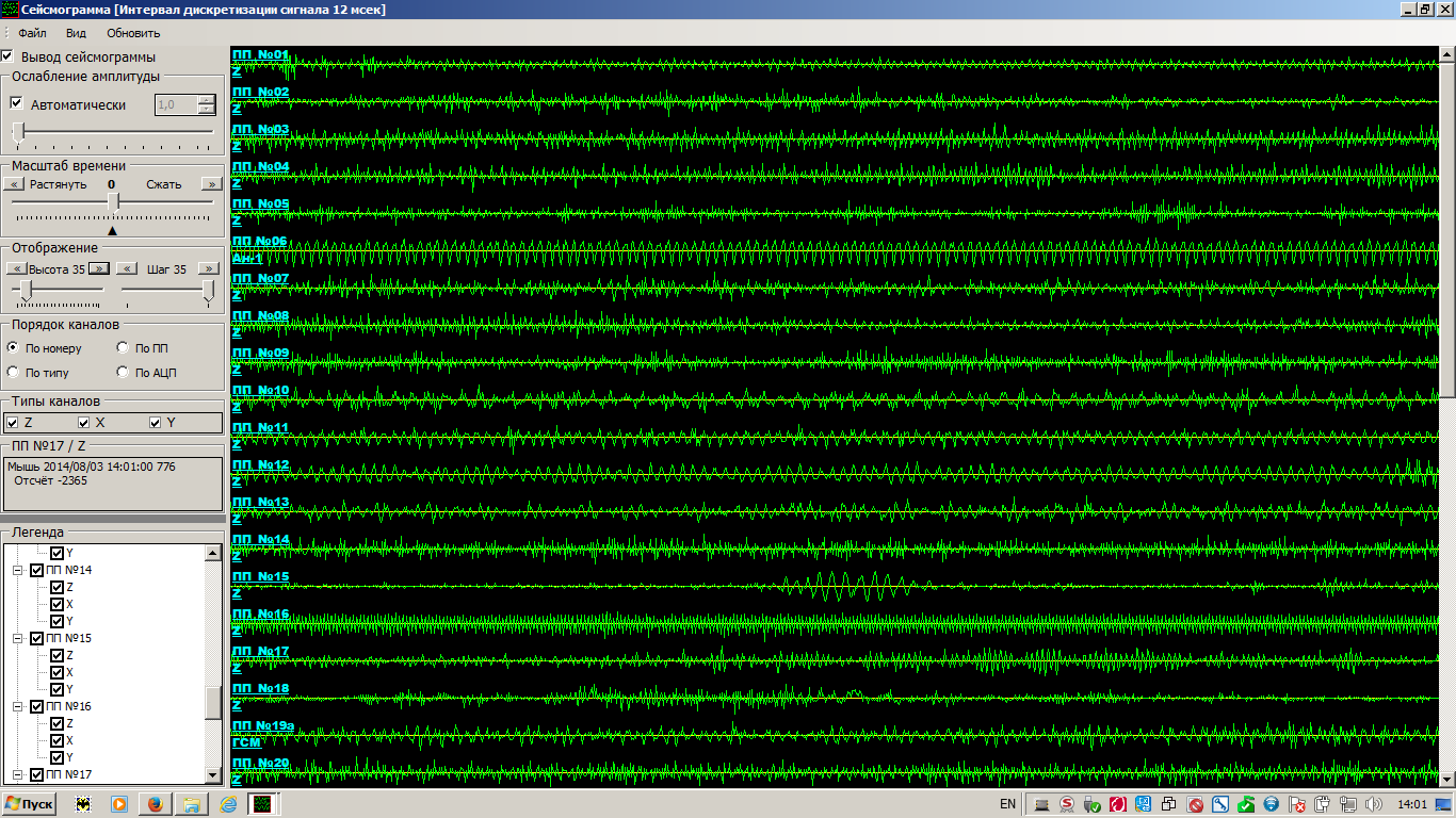
For a direct vision of work of system of seismic monitoring of NSSM, the operator has a possibility of simultaneous viewing of allthe seismic signals in system on the monitor screen in the form of the multichannel running oscillogram in real time. Appearance of the oscillogram of all seismic signals in real time is given in fig. 8. For decrease of load of a data transmission network for formation of the oscillogram the reduced volume of data is transferred. In case of a poor channel capacity of a data transmission network a conclusion of the oscillogram can be turn off.
Principles of the organization of the NSSM system
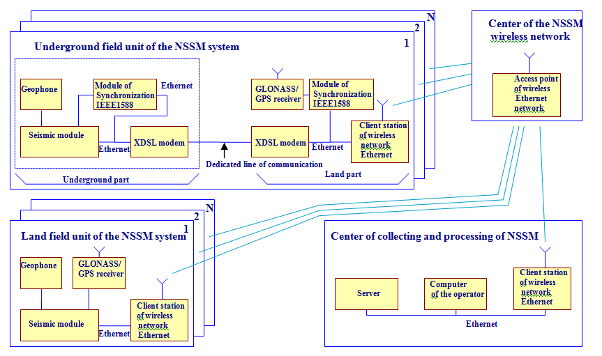
The system of seismic monitoring of NSSM is intended for use as system of the continuous automated monitoring of a stressed state and a shock hazard of the massif of rocks. Important property of system is high efficiency ofcollecting and processing of seismic information. Therefore, an infrastructure basis of system are communication channels for transfer of digital seismic information in the Center of collecting and processing of system. The modern development of the equipment of digital communication is characterized by wide use of the protocols and methods originally developed for the organization of office local computer networks, but in process of widespread introduction of computer technologies in daily practical activities gained broad development and for coverage of the considerable territories. Therefore, at development of the system NSSM use of network based on standards of Ethernet of computer networks was accepted for the organization of information transfer. Such approach allows to apply wide scale of the modern digital telecommunication inventory as a part of system of seismic monitoring and to create the flexible infrastructure of communication channels allowing to use different types of communication depending on an installation site of field units of the NSSM system Ц a wireless communication or connection with use of the dedicated wire lines, or their combinations. At the dense network on small squares it is possible to use the ordinary equipment of local computer networks, and, on the contrary, if necessary it is possible to use optical lines, satellite channels. Indispensable condition of functioning of systems of seismic monitoring is the precise time reference of all recorded information. Land field stations can be synchronized by means of GLONASS/GPS receivers, but for underground field units application of GLONASS/GPS is impossible. Recently the protocol of precise synchronization of time of PTP (Precise Time Protocol) known also under the name IEEE1588 gained serious development. During development of the system of NSSM the possibility of synchronization of the field units established underground from land to receiver GLONASS/GPS through the system of synchronization of time working under the PTP protocol via the Ethernet interface is reached. Considering explained the following structure of creation of network system of seismic monitoring of NSSM, fig. 9 is accepted. The NSSM system consists of the arbitraries number of field units. The geophone, the seismicmodule is a part of each field unit. The seismicmodule receives signals from the geophone, and has an entrance for input of signals of synchronization of time. For communication with the center of collecting and processing the seismic module has the computer Ethernet interface. Communication of land field stations with the Center of collecting and processing is carried out through wireless network Ethernet, synchronization of time of ground field station is carried out from receiver GLONASS/GPS. Communication of underground field units with the center of collecting and processing is carried out to the Earth's surface - through a dedicated wire communication link by means of XDSL modems and further through wireless network Ethernet. Synchronization of time of underground field units is carried out from land by receiver GLONASS/GPS via modules of synchronization IEEE1588 interacting among themselves through the same line of a communication along wires. Thus, the made technical solutions of the NSSM system provide flexibility of architecture of system, both concerning a coherent inventory, and concerning the equipment for synchronization of time.
Roughing-out of the recorded seismic signals and selection of seismic events is made immediately in the seismic module of field unit. Only the marked-out seismic events therefore the common load of the environment of information transfer is small are transferred to the center of collecting and processing. At the same time, all volume of the accepted seismic data registers in the carrier (SD card) in field unit. The written-down information is accessible to retreatment by transfer of all or a part of the written-down information through a communication channel at the request of the center of collecting and processing. Management of parameters of filing and all duties of field unit is made remotely from the Center of collecting and processing. Provided on fig. 9. the structure of the NSSM system is only one option of use of system. Depending on specific conditions of use of system other inventory of communication and other structure of system of seismic monitoring with use of the modules made by Elgeo LLP can be chosen. Main principal specifications of the NSSM system The number of field units – is unlimited Number of seismic channels as a part of field unit – 3, 6. Number of bits of analog to digital converter (ADC) in the seismic – 24 (23+sign). Amplification of the amplifier on ADC input – 1, 10 or 100. Interval of sampling of ADC – 2 ms. Frequency range of the seismic channel – from 0 to 200 Hz. Noise level of seismic channels in a frequency range from 0 to 200 Hz, an effective value – no more than 0,08 microvolts. Dynamic range of seismic channels – not less than 130 dB. Seismic information from each field unit (FU) is transferred to the Center of collecting and processing (CCP) for the telecommunication channel. Check of work of software and installation of parameters is carried out remotely via the telecommunication channel. As the telecommunication channel, any telecommunication inventory having the Ethernet interface can be used. Information from all FU of system is transferred to CCP where are carried out its processing. Information binding to the exact time is carried out in field units by the quartz watch. Stability of the course of clocks is not worse than ±1·10-6. Correction of the course of clocks of land field stations is carried out by the GLONASS/GPS receiver. Correction of the course of clocks of underground field units is carried out by the GLONASS/GPS receiver via synchronization modules under the protocol of precise synchronization of time IEEE1588. Accuracy of synchronization is not worse than 0.1 ms. Power supply of the equipment of field units is carried out from the alternating current power line of 220 V ▒ 10%, 50Hz. The firmware software of field unit provides:
The software of the center of collecting and processing provides:
Geophones
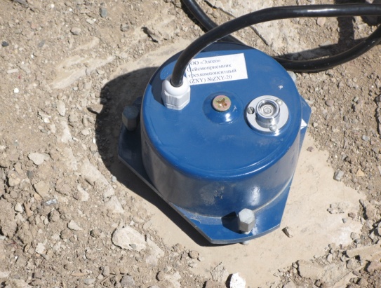
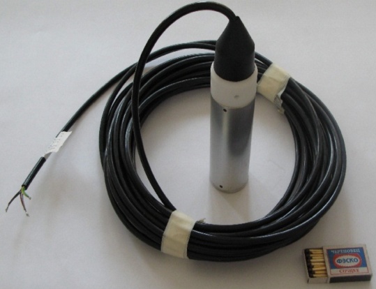
In system of seismic monitoring geophones of any type can be used. Elgeo LLP is ready to deliver as a part of system geophones for the surface installation and for installation in superficial wellsexecuted based on sensitive modules of geophones with own frequency of 4.5 Hz. The system of seismic monitoring can be installed in places with the increased level of the industrialnoise. Therefore, the geophone is mounted in the steel housing which is well protecting from low-frequency electromagnetic disturbances. The geophone has three obstinate screws and bubble level for horizontal installation. The example of installation of the geophone on the concrete foundation is given in fig. 10. Appearance of the geophone for well installation is given in fig. 11.
Design
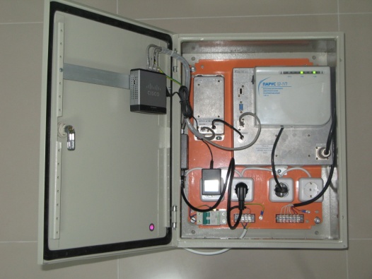
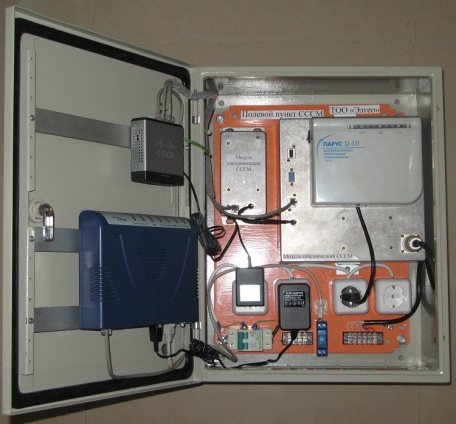
The seismic field unit for underground installation is shown in fig. 13. The module of blue color in fig. 13 - the XDSL modem for dedicated lines.
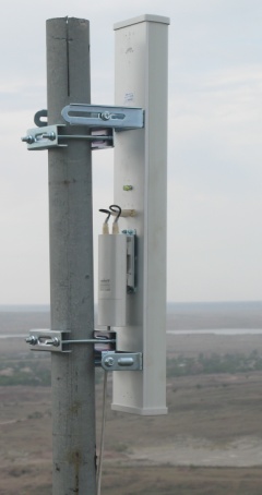
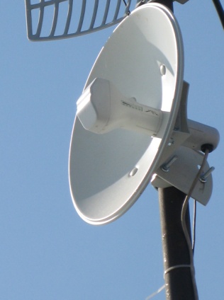
Any modern means of communication compatible to technologies of computer networks can be used to communication of field units with the center of collecting and processing. Wireless computer networks are convenient for the field units established on the Earth's surface. In fig. 14 the access point of the center of a wireless communication network is shown. Client stations of wireless network for communication with the center of collecting and processing are shown in fig. 15 and fig. 16. For communication with the field units established underground in mines, the allocated wire lines, optical lines must be applied.
To download information on the NSSM system.
|